A blog which discusses various GPU applications including visualization, GPGPU and games.

Showing posts with label Direct3D. Show all posts

Friday, February 19, 2010

Tessellation example

Now that I have explained a bit about tessellation, it's time for an actual example. We'll start off with a basic cubic Bézier spline renderer.

Let's start by looking at the parametric function used to compute a cubic Bézier curve. The control points are represented by P0, P1, P2 and P3.

Vertex shader

Recall that the vertex shader is run once per control point. For this example, we just pass the control points through to the next stage.

struct IA_OUTPUT
{
    float3 cpoint : CPOINT;
};

struct VS_OUTPUT
{
    float3 cpoint : CPOINT;
};

VS_OUTPUT VS(IA_OUTPUT input)
{
    VS_OUTPUT output;
    output.cpoint = input.cpoint;
    return output;
}

Hull shader

The patch constant function (HSConst below) is executed once per patch (a cubic curve in our case). Recall that the patch constant function must at least output tessellation factors. The control point function (HS below) is executed once per output control point. In our case, we just pass the control points through unmodified.

struct VS_OUTPUT
{
    float3 cpoint : CPOINT;
};

struct HS_CONSTANT_OUTPUT
{
    float edges[2] : SV_TessFactor;
};

struct HS_OUTPUT
{
    float3 cpoint : CPOINT;
};

HS_CONSTANT_OUTPUT HSConst()
{
    HS_CONSTANT_OUTPUT output;

    output.edges[0] = 1.0f; // Detail factor (see below for explanation)
    output.edges[1] = 8.0f; // Density factor

    return output;
}

[domain("isoline")]
[partitioning("integer")]
[outputtopology("line")]
[outputcontrolpoints(4)]
[patchconstantfunc("HSConst")]
HS_OUTPUT HS(InputPatch<VS_OUTPUT, 4> ip, uint id : SV_OutputControlPointID)
{
    HS_OUTPUT output;
    output.cpoint = ip[id].cpoint;
    return output;
}

Tessellator

The actual tessellator is not programmable with HLSL, but it is worth noting that the actual tessellation takes place between the hull shader and the domain shader. The tessellation factors and compile-time settings (domain, partitioning, output topology, etc.) influence the tessellator.

Domain shader

Note that up until now, we have not used the cubic Bézier curve parametric function. The domain shader is where we use this function to compute the final position of the tessellated vertices.

struct HS_CONSTANT_OUTPUT
{
    float edges[2] : SV_TessFactor;
};

struct HS_OUTPUT
{
    float3 cpoint : CPOINT;
};

struct DS_OUTPUT
{
    float4 position : SV_Position;
};

[domain("isoline")]
DS_OUTPUT DS(HS_CONSTANT_OUTPUT input, OutputPatch<HS_OUTPUT, 4> op, float2 uv : SV_DomainLocation)
{
    DS_OUTPUT output;

    float t = uv.x;

    float3 pos = pow(1.0f - t, 3.0f) * op[0].cpoint + 3.0f * pow(1.0f - t, 2.0f) * t * op[1].cpoint + 3.0f * (1.0f - t) * pow(t, 2.0f) * op[2].cpoint + pow(t, 3.0f) * op[3].cpoint;

    output.position = float4(pos, 1.0f);

    return output;
}
Because this is an example, I omitted optimizations to maintain clarity.

Pixel shader

This is a simple pixel shader that produces black lines.

struct DS_OUTPUT
{
    float4 position : SV_Position;
};

float4 PS(DS_OUTPUT input) : SV_Target0
{
    return float4(0.0f, 0.0f, 0.0f, 1.0f);
}

API setup

Control points are treated the same way as vertices.

Input assembler signature:

D3D11_INPUT_ELEMENT_DESC desc[] =
{
    {"CPOINT", 0, DXGI_FORMAT_R32G32B32_FLOAT, 0, 0, D3D11_INPUT_PER_VERTEX_DATA, 0}
};
Input assembler binding code:

UINT strides[] = {3 * sizeof(float)}; // 3 dimensions per control point (x,y,z)
UINT offsets[] = {0};
g_pd3dDC->IASetPrimitiveTopology(D3D11_PRIMITIVE_TOPOLOGY_4_CONTROL_POINT_PATCHLIST); // 4 control points per primitive
g_pd3dDC->IASetInputLayout(layout);
g_pd3dDC->IASetVertexBuffers(0, 1, &controlpoints, strides, offsets);

// Bind the shaders
// ...

// Render 4 control points (1 patch in this example, since we're using 4-control-point primitives).
// Rendering 8 control points simply means we're processing two 4-control-point primitives, and so forth.
// Instancing and indexed rendering works as expected.
g_pd3dDC->Draw(4, 0);

Now that the shaders are out of the way, it is a good time to explain the purpose of two tessellation factors for isolines rather than just one. Recall that a single tessellation factor can be no greater than 64. When dealing with isolines, this number is rather small; it is desirable to render a single isoline patch with a high degree of tessellation. To alleviate this problem, D3D11 allows us to specify two isoline tessellation factors: a detail factor and a density factor.

To understand what these factors mean, visualize a square. Now imagine that the detail factor describes how much to divide up the y axis, while the density factor describes how much to divide up the x axis. Now imagine connecting the dots along the x axis to form lines.

Another way to think about this: the density factor describes how much to tessellate a line, while the detail factor describes how many times to instance the tessellated line. We can find the location within a tessellated line by using SV_DomainLocation.x and we can find which line we're evaluating by using SV_DomainLocation.y. This effectively lets us chain the lines together into one, ultra-tessellated line. Darn good use of parallelism if you ask me.

Back to the example at hand: let's run some control points through this shader and see what we end up with.

Consider the following control points:

P0 = [-1, -0.8, 0]
P1 = [ 4, -1,   0]
P2 = [-4,  1,   0]
P3 = [ 1,  0.8, 0]


Keep in mind that we're using a hard-coded density tessellation factor of 8 here, which is why the result looks low-resolution. Let's up the factor to 64 and see what we get.


Much better.

There are a number of things we could do to improve upon this example. For example, to obtain more than 64 divisions per patch, we can use the detail factor to "instance" the line up to 64 times, and piece together the instanced, divided lines in the domain shader. Another thing we could do is create a geometry shader which transforms lines into triangles. We could procedurally perturb the control points in the vertex shader for animation effects. We could compute the tessellation factors as a function of the control points.

Saturday, February 6, 2010

D3D11 tessellation, in depth

Consider the typical flow of data through the programmable pipeline:

Input assembler -> Vertex shader -> Pixel shader

Buffers containing per-vertex data are bound to the input assembler. The vertex shader is executed once per vertex, and each execution is given one vertex worth of data from the input assembler.

Say, however, that we wish to process control points and patches instead. The vertex shader by itself isn't particularly well-suited for handling the manipulation of patches; we could store the control points in a buffer and index with SV_VertexID, but this is not very efficient especially when dealing with 16+ control points per patch.

To solve this problem, D3D11 adds two new programmable stages: the hull shader and the domain shader. Consider the following pipeline.

Input assembler -> Vertex shader -> Hull shader -> Tessellator -> Domain shader -> Pixel shader

Normally, the input assembler can be configured to handle points, lines, line strips, triangles and triangle strips. It turns out that it is quite elegant to add new primitive types for patches. D3D11 adds 32 new primitive types: each represents a patch with a different number of control points. That is, it's possible to describe a patch with anywhere from 1 to 32 control points.

For the purpose of this example, say we've configured the input assembler to handle patches with 16 control points, and also that we're only rendering one patch. We will use a triangular patch domain.

Since we're rendering one patch, we'll need a buffer with 16 points in it -- in this context, these points are control points. This buffer is bound to the input assembler as usual. The vertex shader is executed once per control point, and each execution is given one control point worth of data from the input assembler. Similar to the non-patch primitive types, the vertex shader can only see one control point at a time; it cannot see all 16 of the control points on the patch.

When not using tessellation, the next shader stage is executed once the vertex shader has operated on all of the vertices of a single primitive. For example, when using the triangle primitive type, the next stage is run once per every three executions of the vertex shader. The same principle holds when using tessellation: the next stage isn't executed until all 16 control points have been transformed by 16 executions of the vertex shader.

Once all 16 control points have been transformed, the hull shader executes. The hull shader consists of two parts: a patch constant function and the hull program. The patch constant function is responsible for computing data that remains constant over the entire patch. The hull program is run per control point, but unlike the vertex shader, it can see all of the control points for the entire patch.

You might be wondering what the point of the hull program is. After all, we did already transform the control points in the vertex shader. The important part is that the hull program can take into account all of the control points when computing the further transformed output control points. D3D11 allows us to output a different number of control points from the hull program than we took in. This means we can perform basis transformations -- for example, using a little math we could transform 32 control points into 16 control points, which saves us some processing time later on down the pipeline. At this point, further clarification is helpful: the hull program runs once per output control point. So, if we've configured the hull program to output 4 control points, it will run 4 times total per patch. It will not run 16 times, even though we have 16 input control points.

The next stage is the tessellator unit itself. This stage is not programmable with HLSL, but has a number of properties that can be set. The tessellator is responsible for producing a tessellated mesh and nothing more; it does not care at all about any user-defined data or any of our control points. The one thing it does care about, however, are tessellation factors -- or, how much to tessellate regions of the patch. You may be wondering where we actually output these values. Since the tessellation factors are determined once per patch, we compute these in the patch constant function. Thus, the only thing given to the tessellator is the tessellation factors from the patch constant function.

The topologies produced by the tessellator vary depending on how it is setup. For this example, using a triangular domain means that the tessellator will produce a tessellated triangle topology described by 3D barycentric coordinates. How cool is that?

So, by this point we've transformed each control point in the vertex shader, performed a possible basis transformation of the control points in the hull program, and have determined the tessellation factors for this patch in the patch constant function, along with any other user-defined data. The tessellation factors have been run through the tessellation hardware, which has created a shiny new tessellated mesh: in this case, a tessellated triangle described with barycentric coordinates. I would like to emphasize once again that the tessellator does not care at all about anything besides the tessellation factors and a small number of configuration properties set at shader compile-time. This is what makes the D3D11 implementation so beautiful: it is very general and very powerful.

You're probably wishing we could transform the tessellated mesh in arbitrary ways, and, well... we can! The next stop is the domain shader. The domain shader can be thought of as a post-tessellation vertex shader; it is run once per tessellated vertex. It is handed all of our output control points, our patch constant data, as well as a special system value which describes the barycentric coordinate of the tessellated vertex we're operating on. Barycentric coordinates are very handy when working in triangular domains, since they allow us to interpolate data quite easily over the triangle.

At this point, the flow of data is familiar: the output from the domain shader is handed to the pixel shader. It is important to note that in general, 32 float4s can be passed between every shader stage. We can pass 32 float4s from the vertex shader to the hull shader, 32 float4s from the patch constant function to the domain shader, 32 float4s from the hull program to the domain shader, and 32 float4s from the domain shader to the pixel shader. In other words, a lot of data can be passed using interstage registers, not to mention we can also bind shader resource views to the vertex, hull, domain, geometry and pixel shader stages.

I have left the geometry shader out of this explanation to simplify things, but it is very possible to throw a geometry shader into the mix to do some very interesting things -- one example that comes to mind is eliminating portions of a patch, or breaking it up into individual triangles to form new topologies. It is also possible to use stream-out with tessellation.

Due to the general nature of the pipeline, we can even use tessellation without binding any actual control point data to the pipeline at all. Consider that the vertex shader is able to see the vertex ID (control point ID in this case) and instance ID. The hull and domain shaders can see the primitive ID (which is basically a patch ID). Using this information alone, very interesting and useful things can be accomplished: a good example is producing a large mesh consisting of many individual patches. The patches can be placed appropriately by using the primitive ID.

Earlier I touched on the tessellation stages having compile-time settings. These settings are specified with the hull program. Here is an example declaration of settings.

[domain("tri")]
[partitioning("integer")]
[outputtopology("triangle_cw")]
[outputcontrolpoints(16)]
[patchconstantfunc("HSConst")]

domain(x) - This attribute specifies which domain we're using for our patches. In this example, I specified a triangle domain, but it's also possible to specify a quadrilateral or isoline domain.

partitioning(x) - This attribute tells the tessellator how it is to interpret our tessellation factors. Integer partitioning means the tessellation factors are interpreted as integral values; there are no "in-between" tessellated vertices. The other partitioning schemes are fractional_even, fractional_odd and pow2.

outputtopology(x) - This attribute tells the tessellator what kind of primitives we want to deal with after tessellation. In this case, triangle_cw means clockwise-wound triangles. Other possibilities are triangle_ccw and line.

outputcontrolpoints(x) - This attribute describes how many control points we will be outputting from the hull program. We can choose to output anywhere from 0 to 32 control points which are then fed into the domain shader.

patchconstantfunc(x) - This attribute specifies the name of the patch constant function, which is executed once per patch.

Each stage is given different data. To illustrate this, I will show one possible function signature for each stage.

VS_OUTPUT VS(IA_OUTPUT input, uint vertid : SV_VertexID, uint instid : SV_InstanceID);

HS_CONSTANT_OUTPUT HSConst(InputPatch<VS_OUTPUT, n> ip, OutputPatch<HS_OUTPUT, m> op, uint pid : SV_PrimitiveID);
HS_OUTPUT HS(InputPatch<VS_OUTPUT, n> ip, uint cpid : SV_OutputControlPointID, uint pid : SV_PrimitiveID);

DS_OUTPUT DomainShader(HS_CONSTANT_OUTPUT constdata, OutputPatch<HS_OUTPUT, m> op, uint pid : SV_PrimitiveID, float3 coord : SV_DomainLocation);

SV_DomainLocation's type depends on the chosen patch domain. For the triangular domain, SV_DomainLocation is a float3. For the quad domain, it is a float2. For the isoline domain, it is a float2 (for reasons which I will touch on in a future post). n stands for the number of input control points and m stands for the number of output control points.

As stated earlier, the patch constant function (HSConst in this case) is required to output at least the tessellation factors. The number of tessellation factors depends on the patch domain. For the triangular domain, there are 4 factors (3 sides, 1 inner). For the quadrilateral domain, there are 6 factors (4 sides, 2 inner). For the isoline domain, there are 2 factors (detail and density).

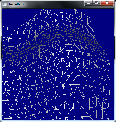
Let's take a look at the topology produced by the tessellator by using the wireframe rasterization mode, a quadrilateral domain, and integer partitioning.

In the following patch constant function, I have chosen to use hard-coded tessellation factors. In practice, the tessellation factors are computed dynamically. The tessellation factors are not required to be hard-coded constants!

struct HS_CONSTANT_OUTPUT
{
float edges[4] : SV_TessFactor;
float inside[2] : SV_InsideTessFactor;
};

HS_CONSTANT_OUTPUT HSConst()
{
HS_CONSTANT_OUTPUT output;

output.edges[0] = 1.0f;
output.edges[1] = 1.0f;
output.edges[2] = 1.0f;
output.edges[3] = 1.0f;

output.inside[0] = 1.0f;
output.inside[1] = 1.0f;

return output;
}


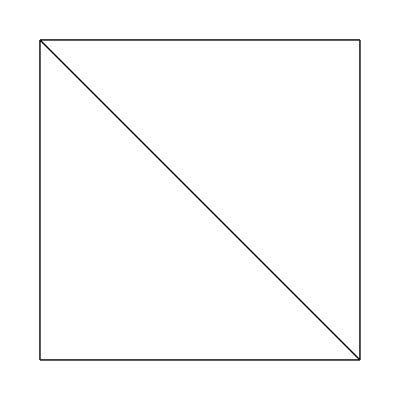
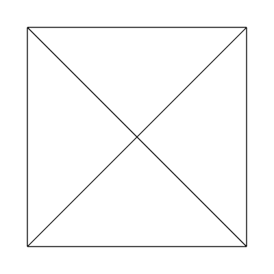
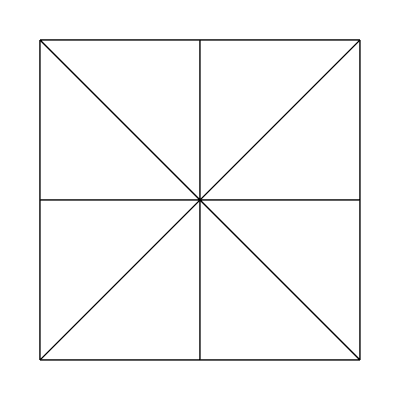
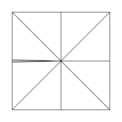
The edge factors are held constant at 1, 1, 1, 1 and the inside factors at 1, 1. The tessellator produces the following mesh:


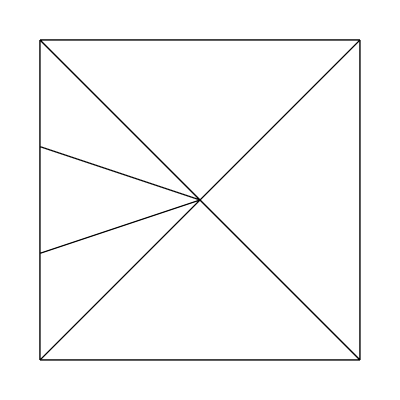
What about edge factors of 3, 1, 1, 1 and inside factors of 1, 1?


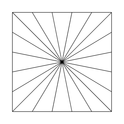
Edge factors of 5, 5, 5, 5 and inside factors of 1, 1:


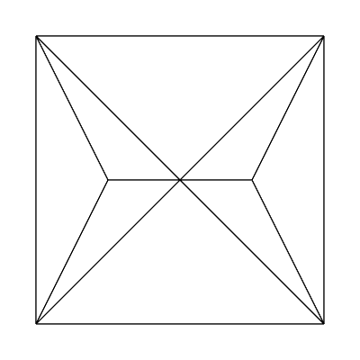
Edge factors of 1, 1, 1, 1 and inside factors of 2, 1:


Edge factors of 1, 1, 1, 1 and inside factors of 4, 1:


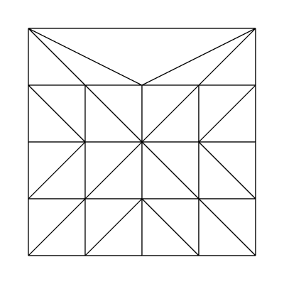
Edge factors of 1, 1, 1, 1 and inside factors of 4, 4:


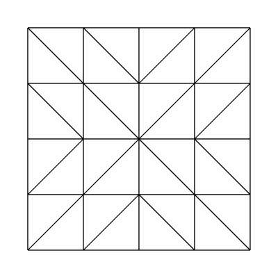
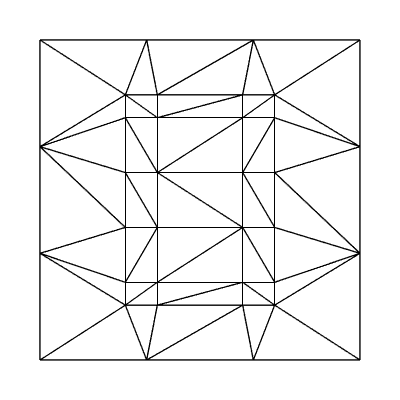
Edge factors of 4, 4, 4, 4 and inside factors of 4, 4:
(Same as edge factors of 3.5, 3.8, 3.9, 4.0 and inside factors of 3.1, 3.22!)


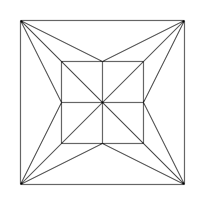
Edge factors of 4, 4, 4, 1 and inside factors of 4, 4:


It should be noted that when using integer partitioning, the implementation is essentially using the ceiling of the written tessellation factors. Let's take a look at the output from the fractional_even partitioning scheme.

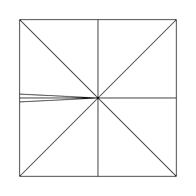
Edge factors of 2, 1, 1, 1 and inside factors of 1, 1:


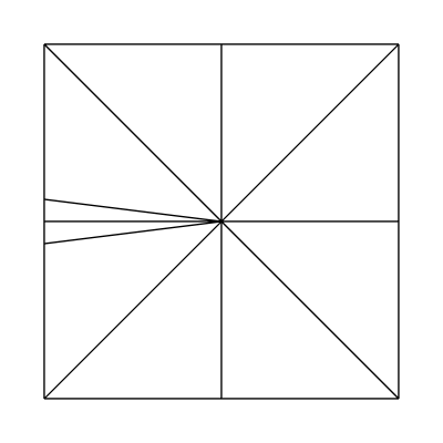
Edge factors of 2.1, 1, 1, 1 and inside factors of 1, 1:


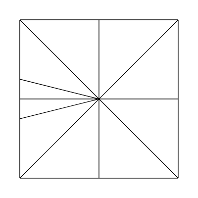
Edge factors of 2.2, 1, 1, 1 and inside factors of 1, 1:


Edge factors of 2.5, 1, 1, 1 and inside factors of 1, 1:


Edge factors of 3, 1, 1, 1 and inside factors of 1, 1:


Here's a funky one with edge factors of 3, 3, 3, 3 and inside factors of 4, 6, using the fractional_odd partitioning scheme:


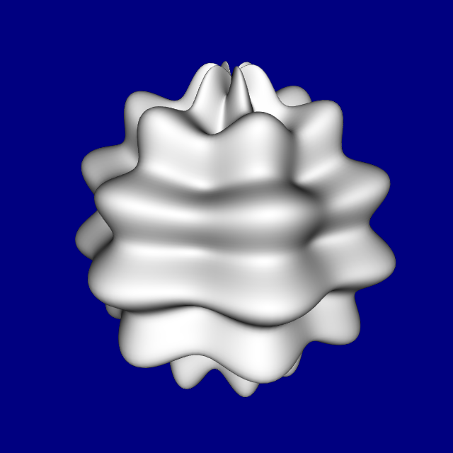
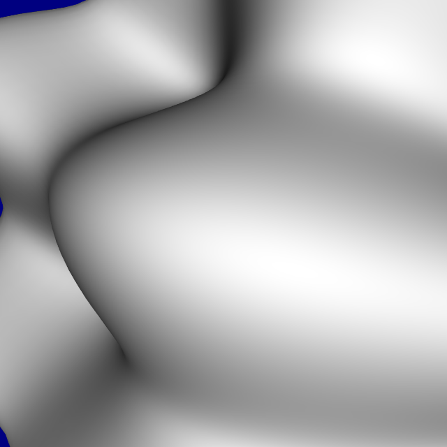
Obviously hard-coded tessellation factors are only so useful. The real usefulness of tessellation comes into play when computing the tessellation factors dynamically, per patch, in realtime based on factors such as level of detail in a height map, camera distance, or model detail.

Thursday, February 4, 2010

D3D11 Resource Limitations

Ever wondered how many resources you can bind to a shader at one time? Or how many slices you can store in a 2D texture array? All of these limits can be found in the D3D header. For D3D11, this is D3D11.h. In this post, I'd like to point out notable improvements in D3D11.

Input assembler binding points (D3D11_IA_VERTEX_INPUT_RESOURCE_SLOT_COUNT): 32, up from 16

Maximum number of layers in a 1D or 2D texture array (D3D11_REQ_TEXTURE2D_ARRAY_AXIS_DIMENSION): 2048, up from 512

Maximum number of interstage float4s: 32 between every stage, up from 16

Maximum size 1D texture (D3D11_REQ_TEXTURE1D_U_DIMENSION): 16384 texels, up from 8192

Maximum size 2D texture (D3D11_REQ_TEXTURE2D_U_OR_V_DIMENSION): 16384x16384 texels, up from 8192x8192

Maximum number of unordered buffers that can be bound to a pixel or compute shader (D3D11_PS_CS_UAV_REGISTER_COUNT): 8, up from 0 ;)

Sunday, January 10, 2010

More tessellator fun

This is just a quick update post on projects I am currently working on.

1. Adding support for the tessellator into my realtime parametric surface plotting program. The original version of this program simply rendered an equally distributed mesh and offset the vertices in the vertex shader. Now I am tessellating patches in realtime to determine how many triangles should be output.

The initial results are promising. Shown here are three images, each of the same plot but with a differing camera position.


2. Music visualization program using wavelets. I plan on bringing the tessellator into this application once I go 3D.

Saturday, September 19, 2009

Tessellator

I finally decided to dive into the new tessellation shaders, and I am quite pleased. Going into it I thought it would be very specific to gaming applications, but as I've found out it is surprisingly general.

New primitive topologies have been added for tessellation. Since the basic unit for the new shaders are patches and control points, the new types allow you to render anywhere from 1 to 32 control points per patch.

Say you're using 16 control point patches. The vertex shader is run per control point, and the output from this stage is passed into the hull shader. The hull shader is really described in two parts; one being a patch-constant function, and the other being the hull program.

The patch-constant function computes user-defined data and is run once per patch. This allows you to compute things that remain constant across the entire patch. The required output from the patch-constant function are tessellation factors: these tell the tessellation hardware how much to tessellate the patch. The hull program is run once per output control point, and both the patch-constant function and hull program can see all control points.

The next step is the actual tessellation, which is performed in a fixed-function, yet configurable stage. The tessellator ONLY looks at the tessellation factors output from your patch-constant function. The user-defined output from the patch-constant function and hull program are provided to the domain shader, which is run after tessellation.

The domain shader is run per-tessellated-vertex and is provided with the tessellated vertex location on the patch. To me it seems that the domain shader can be seen as a post-tessellation vertex shader; this is where you transform the tessellated vertices. The output from the domain shader is provided to the geometry shader (or pixel shader, if not using a geometry shader).

Here are some results from my initial experiments with the new stages:


The toughest part to me is computing the per-patch tessellation factors. But since this is completely programmable, it's a fun problem.

Saturday, August 29, 2009

D3D11 Types

I did some more fiddling with D3D11's new types and have learned new things about them.

First, it seems that it is not possible to read from multi-component RWTexture* and RWBuffer objects due to a hardware limitation. However, it is possible to read-write the 32-bit RGBA type thanks to the way D3D handles views.

Create the texture with a DXGI_FORMAT_R8G8B8A8_TYPELESS format, then for the unordered access view cast it to DXGI_FORMAT_R32_UINT. This allows for a common texture format to be read/written without ping ponging, which is great for in-place transformations.

There is another reason why this is not a major limitation. Consider applications whose requirements are reading and writing a texture, but also use shared memory to reduce texture fetching. This most likely means that there is overlapped texture fetching going on (e.g., for an image convolution), and so ping ponging two textures is necessary here anyway to prevent clobbering of data between shaders.

I have found the new structured buffer types to be much more flexible since they are independent of the texture subsystem. It is possible to read/write any structure and any element of a RWStructuredBuffer. Any shader can read from structured buffers, and the compute and pixel shaders can write to them. According to John Rapp on the DX11 forum, this type also has beneficial performance characteristics.

It should be noted that a structured buffer cannot be bound to the input assembler (not that you'd want to since you can just read from it in a random access manner), and cannot be the output of a stream-out operation. I consider these limitations minimal, since really, the input assembler probably should be going away sometime soon. As for stream out, one can just stream out to a regular Buffer and read from that.

The March 2009 SDK Direct3D 11 documentation mentions that the AppendStructuredBuffer and ConsumeStructuredBuffer types operate similar to a stack in that items are appended and consumed from the end of the buffer. If this is true, this is a very nice property to have. This means it is possible to append to a structured buffer in one pass, and bind it as a plain old StructuredBuffer in another pass (for example, indexed by SV_InstanceID in the vertex shader). Or, filling up a RWStructuredBuffer in one pass, then consuming from it in another pass.

I haven't played around too much with the ByteAddressBuffer type. From my experiments, it seems that StructuredBuffer is the way to go for most things. It seems that these replace Buffer for me in most of my applications.

Sunday, July 26, 2009

Limitations

Having used Direct2D, DirectWrite and the Direct3D 11 previews, I would like to discuss some of the limitations I have run into.

Direct2D has the ability to render into Direct3D textures. However, D2D does not deal with resource views directly; it uses DXGI's facilities to access surfaces. The problem comes when trying to obtain the DXGI surface representation of a 2D texture that has more than one mip in its mipmap chain and/or more than one layer. Unless I am missing something, this is simply not possible. This means that it is not possible to use D2D to render directly into a Direct3D multilayer texture (or mipmapped texture).

Admittedly, I have not found myself needing to do this very often. Indeed, the most useful application of D2D/D3D interop to me has proved to be rendering to the backbuffer, which is neither mipmapped nor multilayered. In one scenario, however, I needed to render some numbers into a texture array. I had to create a temporary texture without any mipmap/layers, render to that using D2D, then perform an on-device copy to get it into my texture array.

This copy could be eliminated in two ways. One way involves adding a D3D dependency to D2D, which is not the best route. The second way involves a modification to DXGI to enable the casting of multilayer/mipmapped 2D textures to surfaces; it would be nice to be able to pass in a subresource number and get a surface representing a particular subresource of a 2D texture.

The second limitation I have run into is in the compute shader. I dislike how the number of threads per group is declared in the shader, and cannot be changed during runtime without a shader recompile. I really do not see the need for this limitation, as both OpenCL and CUDA allow the number of threads per group to be specified at runtime. That aside, I still prefer Microsoft's approach to computation on the GPU. I like that it is integrated into the Direct3D API and uses a language similar to the other shaders.

Aside from these minor limitations, my expectations are definitely surpassed with regard to Direct2D and DirectWrite. I think these APIs fill in a large gap in the Windows graphics API collection.

Monday, March 9, 2009

D3D11 Stream Types

I have been wanting to cover more of the specifics on the new stream data types in upcoming Direct3D 11. Essentially what these types enable you to do is emit data without having to worry about order. That is, these are unordered data types; order is not preserved.

One application of the structured buffer stream types is emitting pixel data in a structure, from the pixel shader. In this scenario, it is necessary to determine how many structures are emitted - luckily, this can be manipulated without ever reading back from the GPU. D3D11 provides the CopyStructureCount method, to copy the number of written items into a buffer. That buffer can then be used with any of the draw indirect methods.

Monday, December 29, 2008

Draw Indirect

Draw indirect is a cool new feature in Direct3D 11 which is basically a more general version of DrawAuto, for compute shaders.

When using stream out with a geometry shader, it is common to want to take the results of one stream out pass and bind it as input to another pass. However, the geometry shader can emit a variable number of primitives; because of this, the programmer must read the number of primitives rendered back from the GPU, causing a stall. To mitigate this problem, DrawAuto was introduced in Direct3D 10 and recently in OpenGL. DrawAuto keeps everything on the GPU by automatically binding the stream out buffers to an input slot and issuing the draw call with the appropriate number of primitives filled in.

Draw indirect takes this one step further by allowing a buffer to be used as the arguments to a draw call. For example, consider the following compute shader.

RWBuffer<uint> args : register(u0);

[numthreads(1,1,1)]
void CS(uint3 id : SV_DispatchThreadID)
{
/* Perform some computation here */

if (id.x == 0 && id.y == 0 && id.z == 0)
{
args[0] = 1000;
args[1] = 1;
args[2] = 0;
args[3] = 0;
}
}

This compute shader writes out 4 unsigned integers to a buffer from thread 0. These values represent the arguments for our draw call.

And on the CPU side of things:

g_pd3dDevice->DrawInstancedIndirect(argsbuf, 0);

The result is the same as if DrawInstanced(1000, 1, 0, 0) had been called. How cool is that?

There are a few draw indirect calls: DrawInstancedIndirect, DrawIndexedInstancedIndirect and DispatchIndirect.

Wednesday, December 24, 2008

GPGPU

General purpose GPU (GPGPU) involves using a graphics card for general purpose computation. It used to be that one would have to perform computations in the pixel shader and render geometry to execute it, which isn't the best abstraction. Recently, there have been developments which allow for proper abstraction: OpenCL, Direct3D 11 Compute, CUDA, etc.

In this example, I have chosen to focus on Direct3D 11 Compute; many of the same ideas apply to the other languages as well. Direct3D 11 Compute is a new type of shader in D3D11 which allows for the explicit usage of shared memory, scattered writes, etc.

As a simple example, say we want to use the compute shader to produce a procedural texture.

RWTexture2D<float4> texrw : register(u0);

[numthreads(1,1,1)]
void CS(uint3 id : SV_DispatchThreadID)
{
float4 color;

color.r = id.x / 255.0f;
color.g = (id.x + id.y) / 510.0f;
color.b = (sin(id.x * id.y) + 1.0f) / 2.0f;
color.a = 1.0f;

texrw[id.xy] = color;
}

Let's take a look at the application-side code.

ID3D11UnorderedAccessView *nullcsview[] = { NULL };
g_pd3dDC->CSSetUnorderedAccessViews(0, 1, &texrwv, NULL);
g_pd3dDC->CSSetShader(cs, NULL, 0);
g_pd3dDC->Dispatch(256, 256, 1);
g_pd3dDC->CSSetUnorderedAccessViews(0, 1, nullcsview, NULL);

There isn't much going on here; I didn't even need to use a compute shader for this. However, it does illustrate one important concept: scattered writes. Notice how I am writing a value to an explicit texel in the texrw texture.

Running this compute shader kernel with 256x256x1 groups and using a simple pixel shader to texture a quad, the results are as follows:

Followers

Contributors