Input assembler -> Vertex shader -> Pixel shader
Buffers containing per-vertex data are bound to the input assembler. The vertex shader is executed once per vertex, and each execution is given one vertex worth of data from the input assembler.
Say, however, that we wish to process control points and patches instead. The vertex shader by itself isn't particularly well-suited for handling the manipulation of patches; we could store the control points in a buffer and index with SV_VertexID, but this is not very efficient especially when dealing with 16+ control points per patch.
To solve this problem, D3D11 adds two new programmable stages: the hull shader and the domain shader. Consider the following pipeline.
Input assembler -> Vertex shader -> Hull shader -> Tessellator -> Domain shader -> Pixel shader
Normally, the input assembler can be configured to handle points, lines, line strips, triangles and triangle strips. It turns out that it is quite elegant to add new primitive types for patches. D3D11 adds 32 new primitive types: each represents a patch with a different number of control points. That is, it's possible to describe a patch with anywhere from 1 to 32 control points.
For the purpose of this example, say we've configured the input assembler to handle patches with 16 control points, and also that we're only rendering one patch. We will use a triangular patch domain.
Since we're rendering one patch, we'll need a buffer with 16 points in it -- in this context, these points are control points. This buffer is bound to the input assembler as usual. The vertex shader is executed once per control point, and each execution is given one control point worth of data from the input assembler. Similar to the non-patch primitive types, the vertex shader can only see one control point at a time; it cannot see all 16 of the control points on the patch.
When not using tessellation, the next shader stage is executed once the vertex shader has operated on all of the vertices of a single primitive. For example, when using the triangle primitive type, the next stage is run once per every three executions of the vertex shader. The same principle holds when using tessellation: the next stage isn't executed until all 16 control points have been transformed by 16 executions of the vertex shader.
Once all 16 control points have been transformed, the hull shader executes. The hull shader consists of two parts: a patch constant function and the hull program. The patch constant function is responsible for computing data that remains constant over the entire patch. The hull program is run per control point, but unlike the vertex shader, it can see all of the control points for the entire patch.
You might be wondering what the point of the hull program is. After all, we did already transform the control points in the vertex shader. The important part is that the hull program can take into account all of the control points when computing the further transformed output control points. D3D11 allows us to output a different number of control points from the hull program than we took in. This means we can perform basis transformations -- for example, using a little math we could transform 32 control points into 16 control points, which saves us some processing time later on down the pipeline. At this point, further clarification is helpful: the hull program runs once per output control point. So, if we've configured the hull program to output 4 control points, it will run 4 times total per patch. It will not run 16 times, even though we have 16 input control points.
The next stage is the tessellator unit itself. This stage is not programmable with HLSL, but has a number of properties that can be set. The tessellator is responsible for producing a tessellated mesh and nothing more; it does not care at all about any user-defined data or any of our control points. The one thing it does care about, however, are tessellation factors -- or, how much to tessellate regions of the patch. You may be wondering where we actually output these values. Since the tessellation factors are determined once per patch, we compute these in the patch constant function. Thus, the only thing given to the tessellator is the tessellation factors from the patch constant function.
The topologies produced by the tessellator vary depending on how it is setup. For this example, using a triangular domain means that the tessellator will produce a tessellated triangle topology described by 3D barycentric coordinates. How cool is that?
So, by this point we've transformed each control point in the vertex shader, performed a possible basis transformation of the control points in the hull program, and have determined the tessellation factors for this patch in the patch constant function, along with any other user-defined data. The tessellation factors have been run through the tessellation hardware, which has created a shiny new tessellated mesh: in this case, a tessellated triangle described with barycentric coordinates. I would like to emphasize once again that the tessellator does not care at all about anything besides the tessellation factors and a small number of configuration properties set at shader compile-time. This is what makes the D3D11 implementation so beautiful: it is very general and very powerful.
You're probably wishing we could transform the tessellated mesh in arbitrary ways, and, well... we can! The next stop is the domain shader. The domain shader can be thought of as a post-tessellation vertex shader; it is run once per tessellated vertex. It is handed all of our output control points, our patch constant data, as well as a special system value which describes the barycentric coordinate of the tessellated vertex we're operating on. Barycentric coordinates are very handy when working in triangular domains, since they allow us to interpolate data quite easily over the triangle.
At this point, the flow of data is familiar: the output from the domain shader is handed to the pixel shader. It is important to note that in general, 32 float4s can be passed between every shader stage. We can pass 32 float4s from the vertex shader to the hull shader, 32 float4s from the patch constant function to the domain shader, 32 float4s from the hull program to the domain shader, and 32 float4s from the domain shader to the pixel shader. In other words, a lot of data can be passed using interstage registers, not to mention we can also bind shader resource views to the vertex, hull, domain, geometry and pixel shader stages.
I have left the geometry shader out of this explanation to simplify things, but it is very possible to throw a geometry shader into the mix to do some very interesting things -- one example that comes to mind is eliminating portions of a patch, or breaking it up into individual triangles to form new topologies. It is also possible to use stream-out with tessellation.
Due to the general nature of the pipeline, we can even use tessellation without binding any actual control point data to the pipeline at all. Consider that the vertex shader is able to see the vertex ID (control point ID in this case) and instance ID. The hull and domain shaders can see the primitive ID (which is basically a patch ID). Using this information alone, very interesting and useful things can be accomplished: a good example is producing a large mesh consisting of many individual patches. The patches can be placed appropriately by using the primitive ID.
Earlier I touched on the tessellation stages having compile-time settings. These settings are specified with the hull program. Here is an example declaration of settings.
[domain("tri")]

[partitioning("integer")]

[outputtopology("triangle_cw")]

[outputcontrolpoints(16)]

[patchconstantfunc("HSConst")]
domain(x) - This attribute specifies which domain we're using for our patches. In this example, I specified a triangle domain, but it's also possible to specify a quadrilateral or isoline domain.
partitioning(x) - This attribute tells the tessellator how it is to interpret our tessellation factors. Integer partitioning means the tessellation factors are interpreted as integral values; there are no "in-between" tessellated vertices. The other partitioning schemes are fractional_even, fractional_odd and pow2.
outputtopology(x) - This attribute tells the tessellator what kind of primitives we want to deal with after tessellation. In this case, triangle_cw means clockwise-wound triangles. Other possibilities are triangle_ccw and line.
outputcontrolpoints(x) - This attribute describes how many control points we will be outputting from the hull program. We can choose to output anywhere from 0 to 32 control points which are then fed into the domain shader.
patchconstantfunc(x) - This attribute specifies the name of the patch constant function, which is executed once per patch.
Each stage is given different data. To illustrate this, I will show one possible function signature for each stage.
VS_OUTPUT VS(IA_OUTPUT input, uint vertid : SV_VertexID, uint instid : SV_InstanceID);


HS_CONSTANT_OUTPUT HSConst(InputPatch<VS_OUTPUT, n> ip, OutputPatch<HS_OUTPUT, m> op, uint pid : SV_PrimitiveID);

HS_OUTPUT HS(InputPatch<VS_OUTPUT, n> ip, uint cpid : SV_OutputControlPointID, uint pid : SV_PrimitiveID);


DS_OUTPUT DomainShader(HS_CONSTANT_OUTPUT constdata, OutputPatch<HS_OUTPUT, m> op, uint pid : SV_PrimitiveID, float3 coord : SV_DomainLocation);
SV_DomainLocation's type depends on the chosen patch domain. For the triangular domain, SV_DomainLocation is a float3. For the quad domain, it is a float2. For the isoline domain, it is a float2 (for reasons which I will touch on in a future post). n stands for the number of input control points and m stands for the number of output control points.As stated earlier, the patch constant function (HSConst in this case) is required to output at least the tessellation factors. The number of tessellation factors depends on the patch domain. For the triangular domain, there are 4 factors (3 sides, 1 inner). For the quadrilateral domain, there are 6 factors (4 sides, 2 inner). For the isoline domain, there are 2 factors (detail and density).
Let's take a look at the topology produced by the tessellator by using the wireframe rasterization mode, a quadrilateral domain, and integer partitioning.
In the following patch constant function, I have chosen to use hard-coded tessellation factors. In practice, the tessellation factors are computed dynamically. The tessellation factors are not required to be hard-coded constants!
struct HS_CONSTANT_OUTPUT
{
float edges[4] : SV_TessFactor;
float inside[2] : SV_InsideTessFactor;
};

HS_CONSTANT_OUTPUT HSConst()
{
HS_CONSTANT_OUTPUT output;

output.edges[0] = 1.0f;
output.edges[1] = 1.0f;
output.edges[2] = 1.0f;
output.edges[3] = 1.0f;

output.inside[0] = 1.0f;
output.inside[1] = 1.0f;

return output;
}
The edge factors are held constant at 1, 1, 1, 1 and the inside factors at 1, 1. The tessellator produces the following mesh:

What about edge factors of 3, 1, 1, 1 and inside factors of 1, 1?

Edge factors of 5, 5, 5, 5 and inside factors of 1, 1:

Edge factors of 1, 1, 1, 1 and inside factors of 2, 1:

Edge factors of 1, 1, 1, 1 and inside factors of 4, 1:

Edge factors of 1, 1, 1, 1 and inside factors of 4, 4:

Edge factors of 4, 4, 4, 4 and inside factors of 4, 4:
(Same as edge factors of 3.5, 3.8, 3.9, 4.0 and inside factors of 3.1, 3.22!)

Edge factors of 4, 4, 4, 1 and inside factors of 4, 4:

It should be noted that when using integer partitioning, the implementation is essentially using the ceiling of the written tessellation factors. Let's take a look at the output from the fractional_even partitioning scheme.
Edge factors of 2, 1, 1, 1 and inside factors of 1, 1:
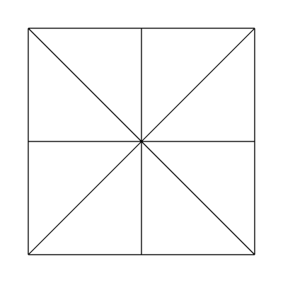
Edge factors of 2.1, 1, 1, 1 and inside factors of 1, 1:
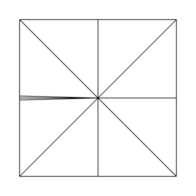
Edge factors of 2.2, 1, 1, 1 and inside factors of 1, 1:
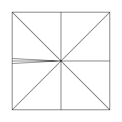
Edge factors of 2.5, 1, 1, 1 and inside factors of 1, 1:
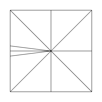
Edge factors of 3, 1, 1, 1 and inside factors of 1, 1:
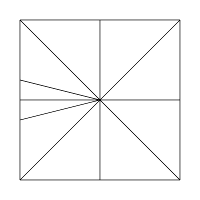
Here's a funky one with edge factors of 3, 3, 3, 3 and inside factors of 4, 6, using the fractional_odd partitioning scheme:
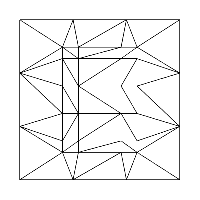
Obviously hard-coded tessellation factors are only so useful. The real usefulness of tessellation comes into play when computing the tessellation factors dynamically, per patch, in realtime based on factors such as level of detail in a height map, camera distance, or model detail.
Thanks for the detailed post. I'm really looking forward to getting a Fermi card and playing around with tessellation.
ReplyDeleteFor me, an obvious usage would be for terrain, however I still don't know what the best way would be for detecting collision with the terrain. Yes, you can stream out the generated vertices, but I imagine that would incur a huge performance hit.
By the way, I am planning on attending the tessellation talk at Gamefest. If I learn anything of interest I'll post it on my blog.
Fermi will be amazing.
ReplyDeleteI am definitely interested in reading about the Gamefest talk -- thanks for the heads up.
FYI, I attended the session at Gamefest. Unfortunately, the entire conference was considered confidential and I had to sign an NDA. So I cannot talk about the tessellation session yet.
ReplyDeleteAw. Hopefully MS posts the presentation soon. :)
ReplyDelete