Let's start by looking at the parametric function used to compute a cubic Bézier curve. The control points are represented by P0, P1, P2 and P3.
Vertex shader
Recall that the vertex shader is run once per control point. For this example, we just pass the control points through to the next stage.
struct IA_OUTPUT
{
    float3 cpoint : CPOINT;
};

struct VS_OUTPUT
{
    float3 cpoint : CPOINT;
};

VS_OUTPUT VS(IA_OUTPUT input)
{
    VS_OUTPUT output;
    output.cpoint = input.cpoint;
    return output;
}
Hull shader
The patch constant function (HSConst below) is executed once per patch (a cubic curve in our case). Recall that the patch constant function must at least output tessellation factors. The control point function (HS below) is executed once per output control point. In our case, we just pass the control points through unmodified.
struct VS_OUTPUT
{
    float3 cpoint : CPOINT;
};

struct HS_CONSTANT_OUTPUT
{
    float edges[2] : SV_TessFactor;
};

struct HS_OUTPUT
{
    float3 cpoint : CPOINT;
};

HS_CONSTANT_OUTPUT HSConst()
{
    HS_CONSTANT_OUTPUT output;

    output.edges[0] = 1.0f; // Detail factor (see below for explanation)
    output.edges[1] = 8.0f; // Density factor

    return output;
}

[domain("isoline")]
[partitioning("integer")]
[outputtopology("line")]
[outputcontrolpoints(4)]
[patchconstantfunc("HSConst")]
HS_OUTPUT HS(InputPatch<VS_OUTPUT, 4> ip, uint id : SV_OutputControlPointID)
{
    HS_OUTPUT output;
    output.cpoint = ip[id].cpoint;
    return output;
}
Tessellator
The actual tessellator is not programmable with HLSL, but it is worth noting that the actual tessellation takes place between the hull shader and the domain shader. The tessellation factors and compile-time settings (domain, partitioning, output topology, etc.) influence the tessellator.
Domain shader
Note that up until now, we have not used the cubic Bézier curve parametric function. The domain shader is where we use this function to compute the final position of the tessellated vertices.
struct HS_CONSTANT_OUTPUT
{
    float edges[2] : SV_TessFactor;
};

struct HS_OUTPUT
{
    float3 cpoint : CPOINT;
};

struct DS_OUTPUT
{
    float4 position : SV_Position;
};

[domain("isoline")]
DS_OUTPUT DS(HS_CONSTANT_OUTPUT input, OutputPatch<HS_OUTPUT, 4> op, float2 uv : SV_DomainLocation)
{
    DS_OUTPUT output;

    float t = uv.x;

    float3 pos = pow(1.0f - t, 3.0f) * op[0].cpoint + 3.0f * pow(1.0f - t, 2.0f) * t * op[1].cpoint + 3.0f * (1.0f - t) * pow(t, 2.0f) * op[2].cpoint + pow(t, 3.0f) * op[3].cpoint;

    output.position = float4(pos, 1.0f);

    return output;
}
Pixel shader
This is a simple pixel shader that produces black lines.
struct DS_OUTPUT
{
    float4 position : SV_Position;
};

float4 PS(DS_OUTPUT input) : SV_Target0
{
    return float4(0.0f, 0.0f, 0.0f, 1.0f);
}
API setup
Control points are treated the same way as vertices.
Input assembler signature:
D3D11_INPUT_ELEMENT_DESC desc[] =
{
    {"CPOINT", 0, DXGI_FORMAT_R32G32B32_FLOAT, 0, 0, D3D11_INPUT_PER_VERTEX_DATA, 0}
};
UINT strides[] = {3 * sizeof(float)}; // 3 dimensions per control point (x,y,z)
UINT offsets[] = {0};
g_pd3dDC->IASetPrimitiveTopology(D3D11_PRIMITIVE_TOPOLOGY_4_CONTROL_POINT_PATCHLIST); // 4 control points per primitive
g_pd3dDC->IASetInputLayout(layout);
g_pd3dDC->IASetVertexBuffers(0, 1, &controlpoints, strides, offsets);

// Bind the shaders
// ...

// Render 4 control points (1 patch in this example, since we're using 4-control-point primitives).
// Rendering 8 control points simply means we're processing two 4-control-point primitives, and so forth.
// Instancing and indexed rendering works as expected.
g_pd3dDC->Draw(4, 0);
Now that the shaders are out of the way, it is a good time to explain the purpose of two tessellation factors for isolines rather than just one. Recall that a single tessellation factor can be no greater than 64. When dealing with isolines, this number is rather small; it is desirable to render a single isoline patch with a high degree of tessellation. To alleviate this problem, D3D11 allows us to specify two isoline tessellation factors: a detail factor and a density factor.
To understand what these factors mean, visualize a square. Now imagine that the detail factor describes how much to divide up the y axis, while the density factor describes how much to divide up the x axis. Now imagine connecting the dots along the x axis to form lines.
Another way to think about this: the density factor describes how much to tessellate a line, while the detail factor describes how many times to instance the tessellated line. We can find the location within a tessellated line by using
SV_DomainLocation.x and we can find which line we're evaluating by using SV_DomainLocation.y. This effectively lets us chain the lines together into one, ultra-tessellated line. Darn good use of parallelism if you ask me.Back to the example at hand: let's run some control points through this shader and see what we end up with.
Consider the following control points:
P0 = [-1, -0.8, 0]
P1 = [ 4, -1,   0]
P2 = [-4,  1,   0]
P3 = [ 1,  0.8, 0]
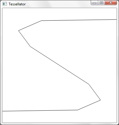
Keep in mind that we're using a hard-coded density tessellation factor of 8 here, which is why the result looks low-resolution. Let's up the factor to 64 and see what we get.
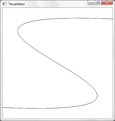
Much better.
There are a number of things we could do to improve upon this example. For example, to obtain more than 64 divisions per patch, we can use the detail factor to "instance" the line up to 64 times, and piece together the instanced, divided lines in the domain shader. Another thing we could do is create a geometry shader which transforms lines into triangles. We could procedurally perturb the control points in the vertex shader for animation effects. We could compute the tessellation factors as a function of the control points.
Wow great posts, 'bout time some tessellation stuff started hitting the blogs.
ReplyDeleteIf you are looking for a topic for your next post, how about looking at importing and tessellating subdivision surfaces :)?
We tried and got an FBX mesh imported into the SubD11 sample, but it wouldn't subdivide. The Samples Content Exporter doco says the mesh should have the "smooth mesh" attribute but we have no idea what that could be..
Thanks. I will try to post another tessellation article soon.
ReplyDelete